Tuesday, August 23, 2016

Racing Seat Bracket

8/23/16
I have since removed this bracket and gone to the PCI Sparco Seat Bracket for concerns of not passing tech inspection with my bracket. Info for it can be found here.


A couple weekends ago I went to an SCCA winter autocross event. Doing so I found out two things: A) I need some practice, B) My head with a helmet sits above the roll bar, which you know, defeats the purpose of it. So I spent the whole time in a sort of scrunched position as to not break the rules. After this uncomfortable experience I decided the next piece going into my car are a racing seat and a harness. 

For whatever reason I have always wanted a car with a racing seat and harness. It just makes me feel cool, even though I am sure it makes me look like a tard. Especially when it takes me a couple of minutes to get the harness on and tightened down. But boy do I feel cool. I put in a Sparco Sprint V seat with a G-Force 6 point harness. The seat fits well inside the car. The shoulder support barely sits against the door when it is closed, and the is mostly because my bracket came out a little skewed. 

For those of you taller people out there looking to race a Miata, especially if you put in a hard dog roll bar like mine, you will need a seat change of some sort and you will likely have to ditch the seat rails and go to a fixed mount. I am 6' 0" and as I said, with the OE seat all the way back and reclined, my helmet lies a good bit above the roll bar. A lot of the aftermarket seats come with simple bolt in options that can use the stock rails or supplied rails. The consensus on this seams to be though is it generally raises people up a 0.5". So I was set on getting a seat and making a fixed bracket system for it.

The first part of this was installing the hard dog harness bar. They make a bolt in harness bar for ~$150 for the shoulder straps. When you take the seat belt tower bolts off there are a bunch of spacers on it. The largest space is the same width and the harness bar mount. So remove that spacer then bolt it on. The only problem I have is that it locks up the rotation of the seat belt. This can be fixed by adding some washers to the assembly. 


The part I am most proud of for this seat is the bracket system that my dad and I came up with for it. I planned on re-using the factory seat mounts and the issue with that is if you want the seat right on the floor and all the way back you can't get to the rear bolts to tighten the seat down. So we took a piece of 1/4" steel and bent it to match the rear mounts. This then provides an opening underneath it which I intended to make a tab to slide under it to hold the seat in place. PRESTO,  you know have a seat the only needs the front two bolts to get it in and out. The rest of the bracket was made out of 3/16" thick by 1.25" wide steel plate. The tab that slides in to lock the rear was just a large piece of angle iron that we had sitting around.


When we were messing with placement of the seat we noticed it was getting caught on some bump that was in the back underneath the carpet. So we pulled up the carpet to find out that it was the plug for the narrow band O2. The seat was snagging on it and would go back or down anymore because of it. So I ended up taking it out of its mounting hole and just taping it to the trans tunnel to get me the extra space I needed. Worked like a charm. Just be careful not to yank the wires if you do this. 


Then came the seat bracket. I have a bunch of pictures of it, and next time it is out of the car I am going to take measurements and made a CAD drawing of it for people to use if they want to make something similar. 


The seat mount holes are at an angle and there is a hump behind them. We did some forming using a vice and a big ass pipe to get the pice to go over the hump and lay flat. To get the front cross piece angle I tacked it on each side and put it in the car and hammered it down to fit, then finish welded it.


So the bracket sets in the car and you slide it back to get the angle iron beneath the rear piece. The two hunks of round steel on the back were scrap we had and I welded the on the set the rear height of the seat. There is still some slop in the seat, you can rotate it some before the tab and the rear piece hit. To fix this I am going to take a thick piece of rubber and put a taper on it and glue it to the rear piece to make an interference fit so the seat doesn't move at all. If you go with something like mine, make sure to gusset the angle iron so it doesn't just bend and break at the weld.


I painted the bracket red and slapped it in. The seat is sturdy as can be and is really painless to get in and out of the car. I am really happy with how it turned out. Getting in and out of the car is more difficult now though. At some point I will take a picture of the bracket by itself and add it. 


Pro Car Innovations - Sparco Sprint V Seat Bracket

I somewhat recently purchased the passenger and driver side Sparco seat brackets from FRSport for the miata. I never felt like the bracket that I made was good enough to pass a real safety inspection as the seat could rotate just a little before the rear 'latch' hit the cross piece. So rather than design and make a new one, I went the lazy route on this. The PCI brackets looked well made and most importantly looked like it would get my seat low while still using the factory mounting locations. The only thing that you have to do for these brackets is, on the driver side only, hammer the trans tunnel in to make clearance. If you look at my post about the bracket I made, I had to do this also. This bracket requires more 'messaging' of the tunnel than what I originally did. But it was easy and I had no problems with a big hammer and a little patience.

I am happy to report that the bracket does keep me really low. I really don't think I can get my seat any lower without having to cut out the factory mounts and make my own. At which point I would still need space for the submarine belt mounts, so I could maybe get another 0.5". The adjustments on the side are also enough that I can get the bracket to work both for me and the lady friend (well close enough for her, we have to bolster her forward just a little extra so she can push the clutch in all the way). But considering I am 6'0" and she is 5'5" (This is a guess), the bracket offers a lot of adjustment.

I am writing this blog entry to show some tricks I have found on getting the seat in and out of the car. If you are short and have the seat mounted forward on the bracket, then it is very easy to bolt the seat to the bracket. Then put the whole assembly in the car and bolt the bracket to the car. But if you run the seat far enough back, like I do, you run into the problem of getting the rear bolts for the bracket in. Well then you have the option of bolting the bracket to the car then dropping the seat in and putting the side bolts in. This would be fine if there was some GOD DAMN clearance between things! You can make it happen but it is slow and frustrating. So below is what what I have found to work the best for getting the seat in and out. I can take the seat out and have it put back in under 5 minutes this way.
Step 1: Start with putting the two front side bolts in. Keep them loose enough that you can rotate the seat around them.

You need to be able to rotate the seat like this.
Step 2: If you have one, get the harness pieces out of the way.

Step 3: Bolt down the front of the bracket. You can make these tight.
Step 4: Rotate the seat up as far as you can.
Step 5: With the seat rotated up, you should be able to reach back in there and get the two rear bolts in and tight.
Step 6: It is still a little frustrating, but now put the two rear side bolts in. I find it easiest to use a ratcheting wrench to help make things go quickly. Tighten down all of the side bolts and you are good to go!
Easy as that everyone. Once you do this a couple of times, you will be able to get the thing in and out if needed in no time at all. Now time for TRACK DAY BRO!

Nothing like a track day with your bro's, even if your car is the slowest one down the straight


Tuesday, July 19, 2016

Eibach Suspension Upgrades

Hey everyone! I have some cool/good news! So this blog was just something that I started to kind of keep track of what I am doing to the car and potentially help people out doing similar things. As of right now I am averaging about 10 views a day. Woh Kanye, in another 5 years my posts are gonna be blowing up bigger than your ego/wife's butt/temper tantrums (take your pick). Why am I trying to make Kanye relevant again?

Alright enough about Kanye, time to get on to what this post is about, suspension upgrades. I have acquired some suspension components from the very friendly company Eibach. I have the Pro-Plus kit. This kit includes a stiffer front and rear sway bar, and a set of springs that lowers the car 1.3" and has a stiffer spring rate. Right now I have a full stock suspension setup. I also have a handy little accelerometer that I made using and Arduino. At my last autocross I used it to collect my max cornering and acceleration G's.

The data can be found in this photo album:
http://imgur.com/a/4oOUV

So we have some stock data, now what? Well I don't really want to put parts on, take parts off, put parts on, take parts off. My intent right now is to put the parts on one at a time and autocross/track the car and see if the max G's change at all. We are mostly looking at corning G's, but it will be interesting to see if accel or braking ones change with the changes. This is also a very simple A to B comparison. At some point I might be smart enough to get my code to do yaw rate and things like that (not even sure right now if the accelerometer that I have will even support that). So take what I do with a grain of salt because it isn't showing the whole picture, but I figured it would be awesome to collect some data and actually show people if any differences occur.

As of right now I have swapped out the front sway bar as that seems to be what everyone says the first suspension upgrade should be. I am a sheeple so that is what I have done.  I have autocrossed with the new sway bar, but due to my own stupidity I forgot the SD card to log data. So that will have to wait till I get a chance to find an empty parking lot or another autocross. The sway bar has definitely decreased the body roll of the car in cornering. At some point I will do some math for you guys to get roll bar spring rates of the stock and Eibach one. I will likely do some other math down the road to do with springs and what damping rate I want. But I gotta learn how to math again first.

One caveat with the springs is that the higher spring rate is likely too much for the stock dampers (not to mention the dampers have 120k miles on them). So when that upgrade happens, there will likely be a damper change too. So count it, that will be TWO things that change at once. Maybe I will put the springs on with the stock dampers for a run just for the hell of it, who knows. I am making it up as I go as always.

Alright enough blabber, time for me to brag about my girlfriend who I forced into driving for the first time at the last autocross. Her times were closer to mine than mine were to the next guy in my class...crap (for me that is). Her fastest run can be found here, look for the pretty and brand new Jag:

Zahra's First Autocross


Wednesday, May 18, 2016

Digital Dash Cluster

Hey all, time to unveil another cool project I have been working on in my spare time. I have been wanting to get an IQ3 dash for the car for a while. I have been told they even make one that just plugs into OBD-II so there is no real wiring required. The unfortunate thing about his dash is that it rather expensive starting at ~$650. Well I am cheap in areas that don't matter and have some skills of my own, so I decided to make my own customizable digital dashboard.

I kept flipping back and forth between using an Arduino and a Raspberry Pi for this project. Both have libraries for reading from an OBD-II serial connection. My gut was to go with the Arduino since I have more experience with the language and I know they are pretty versatile, but I ran into a big problem...displays. There was nothing that I found that seemed easy to implement and would allow for a touch screen without extra code. I also saw this as a good opportunity for me to use a Pi that I had gotten a while back and never used. I have pretty minimal experience with python but took on the challenge anyways.

The parts that I used for this are:

The first thing to note is that the screen is a touch screen, which is really handy for being in the car. This means I can go in and change things or click on things without an attached keyboard or mouse.  The other great thing about it is that there is a sender board with the screen that turns the touch actions into a fake mouse essentially. This sender board then plugs into the Pi with USB and requires no extra programming or wiring! It truly is plug and play!


CRAPPY FLOW CHART
I used whatever the most current distribution of Raspian is for the OS on the Pi. I then set to work with making a python program that would pull the information from the car and send it to a GUI. I chose Tkinter as the GUI package to use (probably wouldn't use again for something more dynamic like this). The screen below is what I came up with for a general layout.


The boxes are changeable to pull the different data that is available over the OBD-II. I have also added color changing such as the coolant cell, where it looks at the temperature coming in and changes the background color of the cell depending on the values. So when the car is cold it is blue, normal operating temperature is gray, and if it goes over a set threshold it turns red. This allows for quick visual analysis of what is happening with the car. This same concept was put into the RPM value, where the number changes colors depending on the value to act as a shift light. COOL STUFF RIGHT! LETS SEE THAT IQ3 DO THAT!

I am still working on the programming, but at some point I intend to add a push button in place of the quit button that will trigger data logging. So you can push it when you want to start and it will save whatever data you have specified to a file and then stop when the car is turned off or if the button is pushed again.

One of the other hurdles that I am trying to get over right now is to set up the Pi so that when the car is turned on it will automatically start his program and make it full screen. I have read some things on the internet on how to do this, but the ones I have tried have not been successful. Any recommendations are welcome. 


Below is the case I designed to be 3D printed to hold it all. I will cut a hole out of the blank gauge plate and then bolt this whole assembly to it. I am still figuring out what I was to do about wiring in the power from the car to the screen/Pi. There will be more on that down the road.


Front of screen attached to 3D printed case
Back side of case and screen

I really hate when people post code for projects like this that are half finished, so at this time I am not going to post my code unless someone asks for it. I will make a second entry about this as I get it put into the car and work out the final bugs with everything. At that point I will release files for the 3D print and the finalized code that I am going to run. SO STAY TUNED!


Monday, March 28, 2016

Roll Cage: Part 1

Hey everyone. Long time no see. Well I am back with another post and this one will likely end up being a couple posts as it was a rather long and arduous project. Assuming that you read the title you already know what I am up to. Building a roll cage for the Miata!

I have owned the car for over a year now and have had some fun doing work on it here and there and getting to drive it in some beautiful areas with the top down. I have enjoyed using it as a real car, but I don't want to forget the whole reason why I bought this car...FOR RACING! At this point in time, the roll cage wasn't really necessary since I am only doing the occasional track day along with some autocrosses. But I we have a tubing bender and making a cage is difficult, so I figured it would be an excellent winter project.

Initial Roll Cage Design

This was the initial design I made for the cage. Using the SCCA rulebook and going off the rules for improved touring/spec miata this is what I came up with. Now like any good project, this is not how it really came out and I will cover each point that is different and why when they come up in later posts. The main requirement of this cage was that I had to be able to fit in it, which as a 6' guy can be a tall order. Hehe, get it! When you look at most cages you can buy on the market, such as the Miata Cage, the main hoops all come down and mount in the corner of the floor pan. The issue with that for me is that I need the seat as far back as I can get it, and mounting there takes up a couple inches of space. So I went with a mount similar to the hard dog roll bar that I had and mounted it to the package tray. So here are some pictures of the "done" cage:


I have gotten to take the car to the final of the winter series autocrosses with the cage done. Here is my quick review of what I like and don't like about what I have done:

With how I have built the cage, the car doesn't seem any stiffer than it did with just the roll bar. The torsional stiffness of the chassis is likely a little higher with the cage, but there are many other suspension reasons on why it doesn't feel any stiffer currently.

With the door bars as they are, getting in and out of the car is actually not too bad. It takes a little longer, but I don't have any problems plopping in and out. Originally I was going to gut the doors and take out the windows, but I am not at that point in my life. So the door bars became a compromise to keep the windows for the time being. 

With a helmet on, I clear everything just barely using the PCI seat bracket. The bracket is a tightfit and took some practice on figuring out how to get the seat in and out efficiently, but I think I have the process down. My helmet does touch the gusset on the side unfortunately, but the only way I can get past that is cutting out the factory seat brackets which I am also not ready to do yet.

Here is my list of cons on things that I did that, if I were to build another cage, I would not do again. I mounted the front feet to the floor pan and had one side welded to the door sill. Many people, like the Miata cage, actually notch the tube and mount it on the door sill. Next time I would definitely do this. I think it would add much more rigidity than I got and you also have much more meat there in the case of a roll over. Same goes with the rear supports. If you take the rear supports all the way into the trunk, you can actually get them mounted on top of the body frame rails. The last big thing that I would do differently is the main hoop. The cross brace on the main hoop still prevents my seat from going as far back as I would like it. You would likely have to cut out the seat belt towers, but I would try and lean the main hoop back ~10° which would give way more clearance.

As far as a first attempt at designing and building a cage, I am pretty pleased with it though. Solidworks FEA was very good and is up to snuff for the SAE roll over standard that all production vehicles must go through. Hopefully I will never have to test it out though.

I will work on breaking the build into some smaller chunks so I can go over all the stuff I learned and changed without make a brick of text.

BONUS:
I drove the Miata down with my very tolerant girlfriend to the final winter series autocross at PPIR. I have not put the soft top back on yet as I am going to have to figure out some method of latching it. So we drove it down at 7 in the morning, with no top, and no heater controls in 20° weather. It should be noted, she is a very very nice lady.


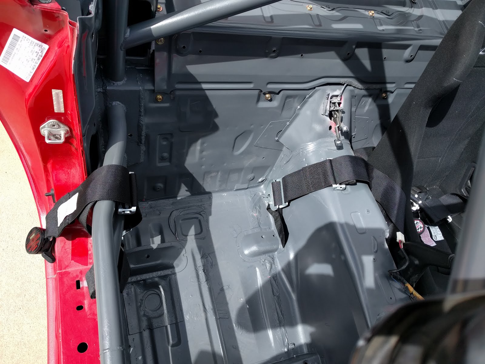
Adding the 6 point harness

If you are going to take the time to put in a racing seat and a roll bar, you gotta have the harness. It adds the extra level on inconvenience for getting in and out of the car to give it that real race car authenticity. If you are scared of drilling holes in the car, this is not for you. How I did it, it only required three new holes and it was super easy to do. In all I got the harness in the car in a little over an hour.

A lot of people with NA Miata's reuse the factor seat belt mounting locations. I did this too, but with my NB the seat belt clip is on the OE seat itself. So that just means we need to drill 3 holes instead of 2. For my harness I got a G-force 6 point, pull down harness. The shoulder straps are wrapped to the hard dog harness bar that I have installed.


You have to drill two holes on the floor for the anti-submarine belt and one on the trans tunnel for the right side lap strap. hehe, lap strap.


For my harness i got a set of the quick release tabs that replace the standard bolt on pieces. This allowed me to just put in eye bolts to clip the harness too. This makes it easy to put in and out. For the factory seat belt hole I got an eye bolt with a 7/16-20 thread on it. This would work but it ended up colliding with my seat, which was a bummer. I have ended up just bolting the left lap strap in and not using the eye bolt. The other three are 5/16 threading. If I got any larger, then the eye portion runs into the bottom of my seat. 

Now for the most important part of putting in a harness. THE BACKING PLATES! Some people on the forums say just use large washers to distribute the load. Well I am trusting my life to this thing and I definitely don't want a mount tearing through the sheet metal. So each of the three smaller eye's has a backing plate from 1/4" steel. I made them as large as the space would allow for a decent amount of load distribution. 


I used Nylock nuts to hold them all in place. Tighten them all down and you are ready to go!


Sunday, January 18, 2015

A/C system delete, NB Miata

TIME FOR ANOTHER EXCITING BLOG POST EVERYONE! Well a couple weeks ago I took what they call the "baby teeth" off my car. This is the act of removing the two tie down hooks on the front of the car. Apparently this is a rite of passage for real Miata owners. Since I am realler than the real slim shady and I believe everything that the internet says I took the 20 minute task to take them off. After proving my worthiness to own a Miata I started my car to let it warm up and check stuff since it had been ~ -20F a week ago. Lo and behold that the radiator was leaking coolant pretty badly. So I did the only sensible thing and rather than try to fix it I promptly went on the internet and bought a more racing friendly radiator to replace it with. I figured while I have the radiator out and I am waiting for the new one I would take the air conditioner out. You can apparently remove the air conditioner without unhooking the radiator, but it is far easier with it out.

I am going to start by addressing all the questions I had when I was looking at doing it as I am sure others will have similar questions. 

Q: What parts do I need to remove the A/C?
A: The only things you absolutely need is an M8 - 1.25 x 45mm bolt and a new power steering (P/S) belt. There is a bolt that holds the A/C bracket on that goes to the oil pump too. If this spot isn't filled oil will leak out. Now for the other things you may want. The cooling unit in the dash can be left in but it is somewhat heavy so I wouldn't recommend leaving it. You can take it out and leave the system unhook or you can get the factory replacement tube for non A/C cars. This weighs almost nothing and will still let you bring in fresh air from the outside. Rosenthal Miata sells this for ~$30 and it comes with the grommets to fill the holes that are left in the firewall. I recommend it. (1999-05 miata non A/C air duct) (P/S with no A/C belt)

Edit: Apparently Rosenthal Miata has shut down and the links are dead. So the part number for the air duct is NA0161150A. There are several retailers that sell it for a similar price to Rosenthal. However, I doubt any other sellers will have it with the firewall plugs, so you guys are on your own for that because I don't have part numbers for those. If someone leaves them in the comments I will add it to this. The PS belt with no AC is also readily available from many places, I am fond of Gates so here is a link to Amazon with the belt.


Q: Since I am removing one of the accessory pulley's, do I need an idler pulley or something to replace the A/C pulley?
A: Nope. The belt tension mechanism is on the P/S unit, so nothing is needed in this case. Just the new belt that will be shorter. I have seen some forum posts that people had concerns about the change in force on the main crank pulley. For scientific reasons I won't go into, it is fine. Just trust me.

Q: Where are some good references on how to take the A/C out since this blog is long winded and I don't really like to read.
     A/C installation instructions - This set of instructions is what everyone uses to do this job. It details how to put A/C in the car, so just work in reverse.

Q: How much weight is this going to save me?
A: I weighed everything I took out and it was 32.0 lbs. Not to mention that your engine isn't running the a/c pulley anymore. That is likely worth at least 50 HP. 

Q: Forums scare me and I still have a questions that has not been answered.
A: Lucky for you there is a comments portion on this and no one ever reads it. So your comments are safe between you and me.However my asnwer may or may not be helpful. May the odds be ever in your favor.

Now we can get to the pictures and stuff! I am not going through the whole removal process since the instructions referenced above are pretty good. I am just going to touch on the things that I had issues with or I had more input for. 

So step one of this whole thing is to get the refrigerant drained out of the system. This should be done by an auto shop or a refrigeration repair person. SAVE THE ENVIRONMENT SO I CAN HUNT POLAR BEARS! It just isn't as fun when they are trying to swim away. 

In standard Ray fashion I was all excited to start working on this and dove in head first and then didn't start taking pictures until I was a good portion in. Maybe one day that won't get the better of me but today was not that day. To give yourself a little room I would take the fan shroud off. The driveer side fan has two bolts on the top holding it in. Remove those and it should pull right out (don't forget to unplug the fan). The passenger side fan has 4 bolts holding it. remove the top two and you only have to loosen the bottom two. The bottom mounts are slotted so they just need to be loose enough to pull the fan up.


Here is the layout of the pulleys if you need a reference:


Next I took off the accessory belt that runs the A/C and the P/S. This garage post on the mx-5 forum has the all the details on loosening and tightening the belts: Accessory Belt Maintenance. The only thing I have to add to this is my bracket was a little seized and I had to loosen the bolt circled in the picture below to get the whole thing to swing down far enought o get the belt off.


Now comes removing the refrigerant lines. Be careful when doing this, as there may still be some pressurized refrigerant in there. So safety glasses are probably a good idea. I removed the two rubber hoses that attach directly to the compressor. Then came pulling off the condenser (radiator that sits in front of the real radiator). I believe this is held on with only two bolts. Mine were super rusted so be prepared for some rust remover spray.

Then I removed the hard lines that run along the passenger side of the engine bay. I removed the brackets that hold them too. 

Once the hard lines are off you can go behind the glove box and pull out the cooling unit. Pull off the glove box and it is the big black box behind it. Take off the two hinge type clips. There are then two nuts that hold the box on, one on the bottom and one one the top. THE TOP NUT IS A REAL BITCH! It is really packed in there. It uses a 10 mm socket and I had to get a universal joint to get the nut because you can't get a straight shot. When you pull out the box the two hose ends that are right at the fire wall come with it. It is easiest if you take the grommets off first. For whatever reason my box was really stuck on the top mounting point. I had to take a screw drive and get it behind the tang and pry on it pretty damn hard to get it to come off.

 If you got the Rosenthal kit, the tube just hooks in. The tube sits on the outside of the white plastic openings. The clips that hold the block box are not reused. The three firewall plugs that come with it cover the two holes where the in and out pipe go through and then the third plugs goes where the drain hose was on the cooling box. 


Don't forget to un-clip the electrical connector. 


 You can kind of see where the top nut is on this picture. The red dot at the top is the threaded post that it is on.

The two front firewall plugs 


Now you can remove the compressor and the accompanying bracket. This part is easy. There are 4 bolts that hold the compressor and 5 that hold the bracket.

The compressor. The four bolts are shown here in the picture 

 I already took out two of the bolts when I took this picture. 


 The shorter bolt is the one that needs to replace the front facing bracket bolt.

The shiny bolt you can see is the one that gets put back in.


You now have the whole A/C System out! Last thing is to put on your new shorter belt for the P/S. Refer to the garage section that I posted on how much tension to put on the belt.


I did nothing with the electrical components yet so I have no input on that. For the two radiator fans, the driver side one is turned on when the engine starts getting hot. The passenger side one is for the A/C unit. My intention is to rewire the A/C fan to just come on when the regular radiator fan is. We will see how difficult this ends up being.


here are all the parts that cam out with my A/C unit.