Sunday, January 7, 2018

Replacing Front Brake Pads and Rotors on the Miata

This post is the second half to the brake changing post. I thought I would separate the front and rear of the car so the posts would be a little shorter. The steps are very similar and if you can do one, you are probably capable of doing the other, but I figured I would capture both since there are a couple differences.

If you are looking for how to do the rear brakes, follow this link to my other post

Doing the pads and rotor vs. just pads on the front end up being even more similar than the rear. For the sake of my laziness, IF YOU ARE DOING PADS ONLY, START ON STEP 7.

Replacing Pads and Rotor

1 .Jack up the front end of the car and support it properly. Then remove the front wheels.

2. Remove the two 14mm bolts holding the caliper on. Once those are out, pull the caliper and old rotor off. Right now is a great time to get a brush and clean off the face of the hub to remove any rust/deformities as you want this surface to be as flat as possible.
Once the old rotor is off, clean off the hub face to make sure it is flat.


3. Remove the old pads from the caliper. Make sure not to damage the two spring clips that are on the backside of the pads.


4. Take some brakleen (or similar) and clean any oil off of the new rotor. It is important that no oil or grease be on the new rotor or pads. At the very least clean the crap out of the face of the rotor that is going towards the inside of the car as it is really hard to clean once installed if you have the OEM brake shield still on.

Clean any oil off of your shiny new rotor

5. Install the new rotor making sure not to touch the braking area with your hands as this can put oil back on the rotor.

6. Now reattach the caliper to the knuckle without any brake pads in the caliper. Tighten the 14mm bolts to their proper torque ( 36-51 lbf-ft) and add some loctite at this time.

I find it easiest to take the old pads out, put the new rotor on, the re-torque the caliper mounting bracket before continuing on


7. Loosen and remove the two sliding pin bolts. Once removed, the caliper body should easily come away from the caliper bracket.


8. Now with the caliper body free and easy to work on, you will need to retract the piston back into the caliper body. If you don't have a dedicated tool for this, it can be done using the old pad and a C-clamp as shown below.

Caliper with piston still out some
caliper with the piston fully retracted

9. Now put on the new brake pads onto the caliper bracket. Make sure all of the little metal retainers are in there and are undamaged.

Caliper with body removed and new pads inserted onto caliper bracket
10. Now add the brake grease to the outside of the pads (They should have their backing plates on). This is also a great time to clean off and grease the slide pins.

Brake pad with grease on it. Make sure to do both sides
11. With everything greased up, slide the caliper body back on over the brake pads and insert the top pin and tighten a little bit. This should keep the body attached but let you rotate it up.

Caliper body re-attached with just the top pin
12. With a little finesse, rotate the caliper body up so you have access to the back of the pads. There are two sets of holes on each pad, one on the top and one on the bottom. Reattach the spring clips by inserting the little ends into these holes. Do this for both the top and bottom. They are oriented as shown below.

The spring clips that attach to the brake pads. It is easiest to do this with the caliper body still over the pads some so the spring clips can't push the pads out of their place on the caliper bracket

13. Now insert the lower slide pin and tighten both pins to 58-65 lbf-ft. Make sure not to damage the rubber boots that sit between the caliper body and bracket that keep water and such out of the pins.


14. Get in the cabin of the car and pump the brake pedal a couple of times to make sure that everything is working and feels like it should. 

DON'T HIT THE BRAKE PEDAL IF YOU HAVE ANY CALIPERS NOT FULLY ASSEMBLED. THIS ISN'T THE END OF THE WORLD BUT WILL JUST MAKE YOUR LIFE HARDER BY EXTENDING THE PISTON AND YOU WILL HAVE TO RETRACT IT BACK INTO THE CALIPER BODY

15. With all this done, you can be on your merry way! Always test the brakes themselves before heading out. Brake pads also have a recommended bedding procedure by the manufacturer. I highly recommend you do that so you get the most out of your new pads.


Replacing Rear Brake Pads and Rotors on the Miata

Well it has been a while since I have written a post because I haven't been doing much to the car right now. It has mostly been sitting as it is leaking oil from somewhere that I can't find. This is making me mad so I was pouting for a little bit, but I got over it and I am ready to get back to it. The goal for this winter is to fix this problem and do some other projects that I have been neglecting on the car. Overall this is the only problem I have seen from the engine rebuild, so that is good I guess!

But before I fix the engine I had a set of new Hawk HPS ceramic pads and new rotors sitting around that I wanted to put on the car. The front rotors are worn to their minimum limit and the pads that I had on the car were metallic and only really worked when rather hot, so I decided to attempt to find a compromise pad that would work for both autocross and track days. The rotors are from Centric Parts. I don't think it is worth spending the extra money for a slotted rotor so I just went with a stock one for now and Centric Part E-coats their rotor hubs which works as a great rust inhibitor. Zinc flake coating like Geomet still works better than e-coat if you find one with that instead.

If you are looking for how to do the brakes on the front, follow this link to my post about changing front pads and rotors

Replacing Rear Pads Only

If you are just replacing the rear pads then follow these instructions. Doing just pads is a very quick process and can be done in under 5 minutes a wheel, assuming everything comes apart smoothly.


1. Jack up the rear end of the car and support it properly. Then remove the rear wheels. 
     
2. The next step is to take the parking brake cable off of the caliper. This is done similar to the throttle body cable if you have ever done that. There are two jam nuts that pinch the bracket that sticks off the back of the caliper. If you can, try to only loosen the nut on the caliper side as moving the nut towards the front of the car can change how much tension is on the passenger cable vs. the driver side cable. This step can also be skipped, but trust me when I say it is worth the minute it will take for you to take off.

Parking brake cable attachment to caliper.

Once the nut is loose enough, you should be able to slide the cable off of the bracket and then pull the end out of its housing and let it hang free so it is out of the way

3. Now there is a cap on the back side of the caliper that is a little hard to see that needs to be taken off. This is the same cap that gets taken off when you adjust the e-brake. Once that is off, use a 4mm (or 5/32 usually works for me) allen wrench and stick it in the hole. Rotate the allen the same direction you did to loosen the cap (righty tighty lefty loose as if you were looking at the bolt head). This sucks the piston back into the caliper body, bring it in until it stops. MAKE SURE WHEN YOU TAKE THE ALLEN WRENCH OUT TO PAY ATTENTION AS THE LITTLE ADJUSTER IN THE HOLE LIKES TO POP OUT WITH IT! DON'T LOSE THAT PIECE!

The caliper piston adjustment hole with the cap removed. Use a 4mm (5/32") allen wrench to adjust the piston in
4. Now it is time to remove the lower sliding pin which is a bolt. It should have a plastic cap covering it that you will need to remove first. The bolt uses a 10mm socket. Loosen it all the way until you can swing the outer portion of the caliper up and away from the brake pads.


The lower sliding pin bolt has been removed and the caliper body can now be slid off of the top pin or left on.
5. Now with the ability to swing (or just take off) the caliper body out of the way, remove the little M shaped springs if you have those. Now you can slide off the old pads and replace them with the new ones. It may not matter, but if your new pads have wear bars on them, make sure the pad with the wear bar is on the inside of the caliper and is on the side towards the ground. If you run it any other directions, I don't know if you will run into fitment problems or not.

NOTE: I highly recommend doing the pads one at a time because if you take both the old pads off before putting in the new ones, you will have to jumble around with holding the little metal retainers if they don't want to stay put while you slide on the new pads.

Old pads were slid off one at a time and replaced with the new pads. Notice the pad with the wear bar is on the inside of the car and the wear bar is towards the ground. I have no clue about fitment for the wear bar in any other orientation

6. Now add the brake grease to the outside of the pads (They should have their backing plates on). I also highly recommend cleaning off the old grease on the slider pins and replacing it with new grease to make sure your brakes can freely move on the sliders. 

Grease the backing plates on the new pads, be sure not to get grease on the rotors or inside of pads
The inner groove on the pads is what slides over the metal clips. This is also proper orientation for the clip if yours pop off and you aren't sure how they go back on

7. With everything greased up, slide the caliper body back on the top pin and rotate it down over the brake pads. Make sure everything is going where it needs to and do not force it down. If it won't go, it is likely caught on something.

Caliper body slid over the new pads

8. Torque the lower pin bolt to secure the caliper body to the caliper bracket (25-29 lbf-ft). Put the M shaped springs on the new pads. Reference the picture in instruction (4) if you need to see how the M springs go on.

9. Now re-attach the parking brake cable in the reverse way of how you took it off. 

10. Lastly, using your allen wrench, adjust the piston outward until the pads clamp the rotor so you can't turn it. From there, back off a 1/4-1/2 turn and make sure rotor can be rotated freely without dragging on the brake pads. Once done, pull on the emergency brake and make sure that it is grabbing good enough that you can't rotate either rotor. If you can rotate one but not the other, you will have to go and adjust the parking brake cable at the caliper where we removed it.

10. Get in the cabin of the car and pump the brake pedal a couple of times to make sure that everything is working and feels like it should.

DON'T HIT THE BRAKE PEDAL IF YOU HAVE ANY CALIPERS NOT FULLY ASSEMBLED. THIS ISN'T THE END OF THE WORLD BUT WILL JUST MAKE YOUR LIFE HARDER BY EXTENDING THE PISTON AND YOU WILL HAVE TO RETRACT IT BACK INTO THE CALIPER BODY

11. With all this done, you can put the piston adjuster cap back on and be on your merry way! Always test the emergency brake and the brakes themselves before heading out. Brake pads also have a recommended bedding procedure by the manufacturer. I highly recommend you do that so you get the most out of your new pads.


Pads and Rotors

If you are also going to replace the rotors then the process is similar to just doing pads but you will have to remove the caliper fully from the knuckle so you can get the rotors swapped. Once you have it down, you can do each wheel in ~15 min. There is going to be some copy paste from the instructions above.


1. Jack up the rear end of the car and support it properly. Then remove the rear wheels. 
     
2. The next step is to take the parking brake cable off of the caliper. This is done similar to the throttle body cable if you have ever done that. There are two jam nuts that pinch the bracket that sticks off the back of the caliper. If you can, try to only loosen the nut on the caliper side as moving the nut towards the front of the car can change how much tension is on the passenger cable vs. the driver side cable. This step can also be skipped, but trust me when I say it is worth the minute it will take for you to take off.

Parking brake cable attachment to caliper.

Once the nut is loose enough, you should be able to slide the cable off of the bracket and then pull the end out of its housing and let it hang free so it is out of the way

3.  Now there is a cap on the back side of the caliper that is a little hard to see that needs to be taken off. This is the same cap that gets taken off when you move the caliper piston to adjust the e-brake. Once that is off, use a 4mm (or 5/32 usually works for me) allen wrench and stick it in the hole. Rotate the allen the same direction you did to loosen the cap (righty tighty lefty loose as if you were looking at the bolt head). This sucks the piston back into the caliper body, bring it in until it stops. MAKE SURE WHEN YOU TAKE THE ALLEN WRENCH OUT TO PAY ATTENTION AS THE LITTLE ADJUSTER IN THE HOLE LIKES TO POP OUT WITH IT! DON'T LOSE THAT PIECE!

The caliper piston adjustment hole with the cap removed. Use a 4mm (5/32") allen wrench to adjust the piston in

4. Remove the two 14mm bolts holding the caliper on. Once those are out, pull the caliper and old rotor off. Right now is a great time to get a brush and clean off the face of the hub to remove any rust/deformities as you want this surface to be as flat as possible.

Once the old rotor is off, clean off the hub face to make sure it is flat. Ignore that I have the caliper bracket still attached in the photo. After doing this a couple of times I found what I think is the most efficient way to change pads/rotors

5. Take some brakleen (or similar) and clean any oil off of the new rotor. It is important that no oil or grease be on the new rotor or pads. At the very least clean the crap out of the face of the rotor that is going towards the inside of the car as it is really hard to clean once installed if you have the OEM brake shield still on.

Clean any oil off of your shiny new rotor
6. Install the new rotor making sure not to touch the braking area with your hands as this can put oil back on the rotor.

7. At this point with the caliper all of the way off it should be pretty easy to remove the old brake pads. Don't forget to remove the M shaped springs if you have those and keep them for the new pads.

8. With the old pads off, bolt the whole caliper back onto the knuckle making sure the rotor is in the groove on the caliper where it needs to be. Torque the two bolts holding the caliper on to 34-49 lbf-ft. It is also recommended that you put some loctite on these bolts.


9. Now it is time to remove the lower sliding pin which is a bolt. It should have a plastic cap covering it that you will need to remove first. The bolt uses a 10mm socket. Loosen it all the way until you can swing the outer portion of the caliper up and away from the caliper bracket.


Remove the lower sliding pin bolt so that the caliper body can be removed from the caliper bracket

10. Now remove the caliper body from the caliper bracket. Take this time to clean off both pins and put some new grease on them to keep them from binding.


11. Install the small metal clips that the pads slide on to and slide the new pads on. I find it easiest to do the most inward one first then the outside one. You should have something that looks like the picture below. It may not matter, but if your new pads have wear bars on them, make sure the pad with the wear bar is on the inside of the caliper and is towards the ground. If you run it any other directions, I don't know if you will run into fitment problems or not.

New pads are installed with the caliper body removed. Notice the pad with the wear bar is on the inside of the car and the wear bar is towards the ground. I have no clue about fitment for the wear bar in any other orientation

12. Now add the brake grease to the outside of the pads (They should have their backing plates on).  

Grease the backing plates on the new pads, be sure not to get grease on the rotors or inside of pads
The inner groove on the pads is what slides over the metal clips. This is also proper orientation for the clip if yours pop off and you aren't sure how they go back on

13. With everything greased up, slide the caliper body back on the top pin and rotate it down over the brake pads. Make sure everything is going where it needs to and do not force it down. If it won't go, it is likely caught on something.

Caliper body slid over the new pads

14. Torque the lower pin bolt to secure the caliper body to the mounting bracket (25-29 lbf-ft). Put the M shaped springs on the new pads.

15. Now re-attach the parking brake cable in the reverse way of how you took it off. 

16. Lastly, using your allen wrench, adjust the piston inward until the pads clamp the rotor so you can't turn it. From there, back off a 1/4-1/2 turn and make sure rotor can be rotated freely without dragging on the brake pads. Once done, pull on the emergency brake and make sure that it is grabbing good enough that you can't rotate either rotor. If you can rotate one but not the other, you will have to go and adjust the parking brake cable at the caliper where we removed it.

17. Get in the cabin of the car and pump the brake pedal a couple of times to make sure that everything is working and feels like it should. 

DON'T HIT THE BRAKE PEDAL IF YOU HAVE ANY CALIPERS NOT FULLY ASSEMBLED. THIS ISN'T THE END OF THE WORLD BUT WILL JUST MAKE YOUR LIFE HARDER BY EXTENDING THE PISTON AND YOU WILL HAVE TO RETRACT IT BACK INTO THE CALIPER BODY

18. With all this done, you can put the piston adjuster cap back on and be on your merry way! Always test the emergency brake and the brakes themselves before heading out. Brake pads also have a recommended bedding procedure by the manufacturer. I highly recommend you do that so you get the most out of your new pads.

Shiny new brakes!


Monday, March 13, 2017

Bolts and clamp load

I am about to go on a diatribe so get ready! At work I have done a lot of clamp load testing of bolts. How this process works is, using a load cell, you take a bolt and torque it to a given amount and see what the force in the direction of the axis of the bolt is (the force between the bottom face of the bolt and the top face of the nut, aka bearing surfaces). If this is done in increments you can even make a chart and map the clamp load vs torque all the way to failure. This is the best way to find the maximum strength of a bolt and how to determine the safe usable proof load for a bolt. From this testing I have learned that not all bolts are made equal! Two M18x1.5 bolts torqued to 100 lb-ft will produce VERY different clamp loads depending on things like: bolt grade, bolt coating, locking nuts, thread lubrication, and thread class to name a few.

Clamp Load

It depends on what style bolted connection you have, but typically clamp load is what is doing the work to keep things in place, not the bolt itself. An example of a connection that uses clamp load is a typical A-Arm style control arm. The arm has a bushing in it, which goes between a clevis and is bolted together with a bolt. Once the bolt is torqued down and everything is properly assembled, the face of the bushing that is interacting with the inside face of the clevis should never slip. If it does it means the suspension was either overloaded or the clamp load wasn't high enough.

Front Upper Control Arm on a Silverado 1500. Consists of a control arm with a bushing being pinched between a clevis on the frame.
Many people have the miss conception that if the bolt isn't a tight fit to the inside of the bushing that you can get movement or compliance. Well this is sure true if the clamp load isn't high enough, which would allow the arm to be pushed/pulled in the pocket from the driving forces. But that is not how these were design to operate. How this is supposed to work is when the bolt is torqued to the specified torque, it produces enough clamp load on the bearing surface of the bushing that the forces in the suspension will not be able to overcome the friction between the two faces. This means that if you can safely get the same amount of clamp from an M12 as what is required for an M14, then the M12 can be used without worry and everything would operate just the same! If you are familiar with eccentric bolts for suspension alignment, then you know this is how these work. Lets say a control arm has a bushing that uses an M14 bolt. An eccentric has a lobe on it that is the size of the M14, then they have to downsize the threads to allow the bolt to rotate to get an alignment change. Typically they are one size smaller, so an M14 eccentric will have M12 threads. This down sizing often means that the eccentric bolts need to be increased in grade (such as from 10.9 -> 12.9) to be able to achieve equivalent clamp loads.
SPC EZ cam Eccentric Bolts
(http://www.spcalignment.com/partimages/81270.jpg)

To the end user, clamp load is the by-product of the given torque value. For a bolt, the higher the torque value the higher the clamp load produced, until the yield point of the bolt is reached. So when manufacturer gives a specific torque spec, they are actually assuming they will get a given clamp load output. This torque to clamp load number is determined through testing the bolt on a load cell with a calibrated torque wrench.

One thing that should be noted is that equivalent bolts will fail at the same total amount of clamp load whether or not they are at the same torque. Lets say there is a bolt that fails at 30,000 lbf of tension. One bolt is coated in a low friction coating and one in a high friction coating. Both bolts are still going to fail when they reach 30,000 lbf of tension, but the low friction coating will reach that amount of clamp at 100 lb-ft while the high friction one will take 200 lb-ft.

What Affects Friction

Anything that can change the friction will affect the amount of clamp load that can be obtained for a given torque. While people often think that it is the friction in the threads that plays the largest role, it is actually the friction between the bearing surface of the nut (or bolt, depending on which you are spinning) and whatever surface it is being clamped against that causes the most drag. Typically a large bolt that needs to reach a high clamp load has certain measures to lower the friction on these surfaces so you can reach the desired clamp load more easily.

Every different coating has a different coefficient of friction which can make reaching your desired clamp easier or harder. The coating can be one of the main contributors to this. You will see that most of the bolts on a modern car use a zinc flake coating, such as Geomet. There are several different variations of this coating even some that have special additives to help make the coating as slick as possible so you can reach really high clamp loads without having to need a torque wrench that goes up to 600 lb-ft (yes I have one this large at work, it is huge).

The other factor that I have seen that plays a large roll is the bolt/nut grade. The higher the grade of bolt, the harder it is. The added hardness helps keep the friction down on the mating surfaces.

Lubricating the threads can also be very effective depending on what you are using for lubrication. ARP bolts come with a pouch of a very specific lubrication that is supposed to be coated over the threads and on the bearing surface of the bolt. They do this to help lower the required torque and to get more consistent clamp loads without necessarily having to go to a torque to yield bolt.

A direct quote from the ARP website -
"We recommend using ARP Ultra-Torque lube to ensure an even, accurate clamp load and to prevent thread galling. This is particularly important for stainless steel fasteners. The lube should be used under the head of the bolt or the bearing surface of the nut and on the threads, unless a thread sealer is used."

Torque to Yield


So we have seen there are a lot of factors that can change what the clamp load is for a given torque on a set of bolts. So what if a precise amount of clamp load is needed, such as on a valve head? If there is a large variation you can warp the head and get bad sealing with the cylinder, thus shortening the engines life. The answer to this question is torque to yield bolts!

Stress Strain Curve
(http://www.metalformingmagazine.com/assets/issue/images/2014/05/Science/Fig1.jpg)

From the chart above it can be seen that once the bolt gets into the yield region (past the yield strength point and before ultimate tensile strength) the curve flattens out a lot. By using this relative plateau a bolt can get very consistent clamp loads across bolts. If you were to torque 100 bolts into the yield region and 100 bolts to something below the yield region, your variation on the torque to yield bolts would be dramatically less.

The best way to tell if you are working with a torque to yield bolt is that the torque spec will have a torque value then an additional angle to turn the wrench. Such as, 100 lb-ft + 90°. This is typically a dead giveaway that it is a torque to yield bolt.


Wrap-Up


Below is a an example of what testing a series of bolts looks like. All the bolts tested were milled M14x2.0, with clear zinc coating, and grade 10.9. It can be seen they all begin to yield around 24,000 lbf, but they don't all fail at the same torque. This is because of varying amounts of friction from tolerances and other factors. Looking at 150 lb-ft of torque on the chart, the spread from the bolt with the lowest clamp load to the bolt with the highest clamp load is 5000 lbf! This difference is likely more than your car weighs! Think about that for a second next time you decide to torque an important bolt without a torque wrench, because even with a torque wrench you can be getting this kind of spread.


So now you know the basics of how clamp load works. Knowing this information can be a huge help when working on anything. It is very important that you follow specific torque requirements if the manufacturer gives them along with any special instructions such as the ARP bolts where they are supposed to be coated in the ARP lubricant. If instructions like this are ignored or not followed correctly, you risk both over tightening or under tightening depending on what you do to the bolt before installing it. Engineers get paid good money to figure this stuff out, you guys should trust them. Maybe not me, but you should definitely trust other engineers.


Sunday, March 12, 2017

Radiator Relocation

Well hello everyone. I have terrific news! I got the engine back in the car and got everything put back together and she fired up! Bad news is I am having a weird oil pressure gauge and a non-functioning alternator problem. But that is neither here nor there.

As an initial warning, to do this you need to have removed the AC and the condenser so there is open space in the front of the car. You could do this with any radiator really.

I figured I would write a quick post about something I spent a couple of hours on this weekend which was relocating my radiator. By relocating, I mean moving it ~2" towards the front of the car. This came about when I was trying to get the radiator and the fans back in the car. The power steering lines got tweaked or something and where I originally had very tight clearances, I now had none. The fan was hitting both the power stearing lines and the sway bar. I have a mishimoto radiator which is a fair bit thicker than the OE one. This has caused me only minor problems since day one, but now has serious problems since I couldn't even get the fan in the car.


 Well shit, now what? Looking down at the bracket that holds the radiator I saw the holes where the condenser used to sit since I took the AC out and nothing sits there now. I tried to get the radiator in there...no dice. But hey anything can be modified!

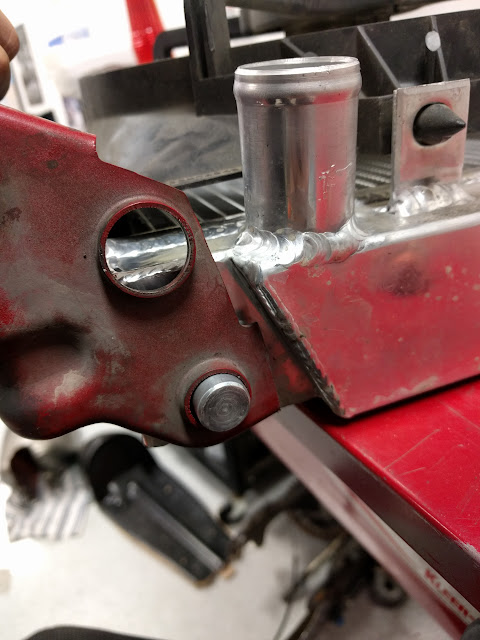
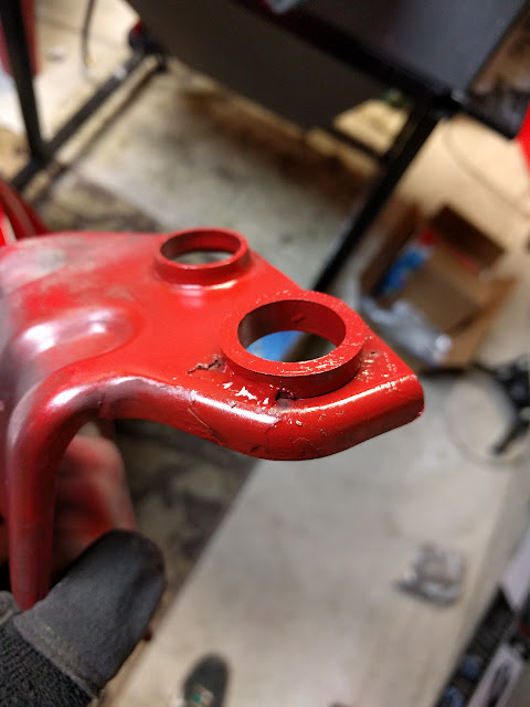
The condenser whole is the one towards the bottom of the photo. This was after modifying it, you can see it is about the same size as the original radiator mount hole.
In short what I did was took the brackets off. I had to cut off a corner on the driver side bracket that wasn't doing anything anyways to make clearance for the radiator. I then opened up the condenser mount holes to be 1" and then cut two adapter pieces to fit in the hole and welded them to support the radiator. After this I had to bend the top supports a little extra to have a good fit. All you need to do for that is put them in a vice and hit them with a hammer. Go easy though, they bend fairly easy.


Thursday, February 16, 2017

Life Update

Hello everyone. So I started this blog to help capture the stuff I am doing with the miata and to ideally help other people out there. Not to give you life updates about me because lets be honest, you don't give a shit about me personally (if you do then I guess lucky me, woopy!). I have been waiting to post the final installment of my engine rebuild (the put all this shit back together post). The waiting has been because I have needed to buy the new clutch and flywheel for the turbo upgrade down the line. I just got them in this past week and am hoping to get the car back together and running in March some time.

I wanted to give a quick life update to why the last installment has been slow. It is something that I have been back and forth on for a while now. If you know me personally, you know I won't shut up about the Focus RS. I WANT ONE REAL BAD. However, I am smert and don't want one yet while they shake out the bugs on the new platform. Ford has also talked about putting in a dual clutch transmission in this car in the near future. I don't know if that will happen or not but...I ALSO WAAAAAAAANT. So I have been idly sitting by driving my 10 year old civic that runs great and I have no complaints about until I am ready to pull the trigger on an RS. Well, I couldn't handle it anymore. I WANT A NEW MORE FUN KER WHILE I WAIT! So I went with what I believe to be the most fun per dollar currently on the market:


I done bought a 2016 Fiesta ST. I have zero buyers remorse on this little car. I still giggle every time I punch the gas pedal. I currently don't plan to do much to this car, but as always that is likely to change as I can't leave well enough alone. Which is proved by the fact that I already pushed an unofficial SYNC system update so I could have android auto because Ford has been hella slow on this. So you might see a post from time to time about this naughty little speeding ticket waiting to happen.


Anyways, this is my new baby along with my other cars. I officially own too many cars and am rapidly turning into my father. So there you have it, I have a sweet new car and the Miata is still slowly progressing to being running again. I will have it running in time for the first Autocross of the season!

Sunday, December 25, 2016

Engine Rebuild - Part 2: Engine Mounting and Dissasembly

Now we are getting to the topics that I really wanted try to cover more in depth. Anyone can take an engine out of a car and take it apart, but getting it back together and getting to to run, THAT MY FRIENDS is a challenge.

I covered this in the engine removal post, but I rebuilt my engine because my crank bolt was loose and had chewed into the keyway a little bit. Mine was no where near as bad as other I have seen on the internet. I do believe it was bad enough that I was running 1-2 degrees retarded timing. I can't currently confirm this because I didn't think that was the problem at the time and I took it all apart and didn't want to put it back together to check it with a timing light. But I will say, while I am not the best driver in the world, I was being beaten by completely stock Miata's at autocross events by ~4 seconds depending on the course. So we will see if this helps liven up the motor a little bit and help with that.

If you have a worn out keyway, one option to fix it rather than take the whole engine apart and replace the crankshaft like me is to use Loctite 660 to repair it. There are plenty of walk-throughs out there that show you how to do this. Loctite 660 is specifically made to repair bad keyways in machines and people seem to have good luck with the fix if yours isn't too worn out. My engine was a good candidate for this fix, but now that I plan to turbo I was going to replace the piston rods anyways.

Lastly, before we get into it, if you want to rebuild an engine but are afraid of tackling a project like this, it really isn't that bad. If your car is a fun car and isn't needed for daily driving or anything like that, I highly recommend picking up a Grainger Manual (or similar) and learning something new. This book walks you through how to rebuild an engine and is a great resource for plenty of other maintenance things. On top of that, if it is a miata you have, there is no better car community out there willing to help people solve problems. You are all wonderful people and I thank everyone who has helped me get my car to where it is today!

Preparing the Engine for Work

You are going to want to clean the engine as best you can. As the parts come off you will be able to clean them better, but it is helpful to start with a clean engine. Use some engine de-greaser, a brush, and a hose to clean off what you can. Of course mind the electronics when you do this. If you didn't already do it in the car, while the engine and transmission are on the hoist, NOW is the time to drain the rest of the fluids and let it sit for a little. 

In usual Ray fashion, I didn't take any pictures of this process, but next you need to unbolt the transmission and put it somewhere. The thing ways ~60lbs, it is pretty easy to carry by yourself, but as always have a second hand or set it up on something in case you have problems. Next is the flywheel. This likes to spin while you try to get it off. Use either an impact gun, or a decent sized flat blade screw driver and put one of the transmission bolts back in for leverage to hold the thing. You should now have access to the back of the engine to mount it to the engine stand.

Engine Mounting

First thing is first, you need to get the engine somewhere that you can work on it. I had an engine stand and I welded up some fingers to use to attach it since the originals fingers were missing from the stand. If you want to make your own I used:

I am going off memory about this as I don't have them right in front of me right now, but I believe I cut (4x) 6" sections of square tube. I drilled them to .625" so the tube would slide through. I then cut (4x) 2" sections of the round tube and slid them in and welded them. I then marked the hole locations for the plate that was on the engine stand and drilled them out. Then I bolted it all together as seen below. I may have made adjustments from what I have above, so double check your work as you go through this. 


Removing External Components

Next is to start removing everything still attached to the outside of the engine. Depending on what you took off with it still in the car this might vary. But I had to remove things like the intake manifold, fuel rail and injectors, EGR components, misc brackets. This part is easy to do and because of that it is easy to do it quickly and forget to label stuff! LABEL EVERYTHING AND TAKE PICTURES OF EVERYTHING. I was trying to be really conscious of this while I was removing stuff, but as I put it back together there have been plenty of mystery parts that have taken a fair bit of time to figure out where they go.

A smattering of the photos I took

Remove the Rest!

With all the external components off you should have a basic looking engine with an oil pan, block, cylinder head, and valve cover, plus or minus a couple of things. Start by removing the valve cover. The Grainger manual recommends starting in the middle and spiraling outwards to loosen AND tighten the bolts. While I can see this for tightening them, I am not sold on it for loosening. But DO IT ANYWAYS, it surely won't hurt. 


With this off you will be able to see the bolts holding the cylinder head on. Do the same process as the valve cover. Start in the middle and spiral out to loosen these and take the cylinder head off.


You should be left with something like I have shown above. I will not be covering how to adjust the valve lash and stuff for the cylinder head as I had someone do the work for me. It was ~$275 to get the valve seats re-cut, the valves ground, seals replaced, lash adjusted (with the stupid shim type system), gaskets replaced, head checked for flatness and re-milled, and likely a couple other small things I am forgetting. If you want to do it yourself, great! But I recommend letting someone who has done a ton of them do it for a reasonable price unless you have the proper tools.

Now we turn the engine over to get the oil pan off. Remove all of the bolts around the pan. Using a small screwdriver or sheet rock knife, break the seal of the pan to the block. HERE IS WHERE THINGS CAN BE TRICKY! Mine was so covered in sealant I couldn't see where it was, but there is an oil baffle that gets sandwiched between the oil pan and the block. When you break the oil pan free, if the baffle is still stuck to it, you won't be able to get the oil pan off. It will seem loose but something 'springy' will be keeping it held on. If this happens DO NOT PULL ON THE OIL PAN! YOU HEAR ME! You will need to take you knife and cut along the sealing surface of the pan to try and cut/pry the baffle off of the oil pan.

This is the baffle and the block still together. The oil pan sits on top of the baffle and sandwiches it between it and the block

The baffle is bolted to the oil intake tube, which is why you don't want to pull on it too hard. If you do, you risk bending that tube which you will then need to replace. 


Remove the Crank, Pistons, and Oil Pump

BEFORE YOU DO ANYTHING, take 4 paper towels and label them Cyl #1, Cyl #2, Cyl #3, and Cyl #4. If you plan on re-using any of the internals, you need to keep track of where they all go, If you are replacing everything, then this part is good to still do in case something goes wrong and you end up needing something. With the engine still flipped over, you now have access to the crankshaft and main bearings. Rotate the crank shaft to some point where you can access all the rod end caps.

Take a punch and punch the bottom of the end caps with a dot(s) for what the cylinder number is. 1 dot for cylinder 1, 4 dots for cylinder 4. With this done you can now loosen and remove the end caps, putting them and their bearings on the respective paper towel. CAREFULLY push the pistons down to a point where they are out of the way as you will likely not be able to get them out at this time.

Loosen and remove the crankshaft main bearing caps. These should all be labeled and with an arrow that points to the front of the engine. Double check and remark if you are uncertain about the markings on some. Make sure to get the thrust washers off of the fourth main cap. With these removed, the crankshaft is now loose and can be carefully lifted out of the engine. Make sure not to scratch the journals on the piston rods or anything else. 

With the crank out, you can now push the pistons the rest of the way out. There is likely carbon build up on the top side of the cylinders. This may need to be cleaned off with some carb cleaner and elbow grease before the pistons will slide out. Remove the oil sprayers that are on the bottom of the cylinders and keep them with the correct cylinder. Mine had no copper washers, but it seems like the pre-NB 1.8L engines had them.

If you have not already, remove the oil pump.

Using your punch, mark the piston rods and the bottom side of the pistons in the same fashion as the bearing caps for the cylinders that they correspond to.


You should now be left with an empty cylinder block ready for work! The coming post after this one will be about putting it all back together. MERRY CHRISTMAS TO ANYONE READING THIS TODAY!